RISCVBusiness Overview
RISCVBusiness is intended to be a configurable RV32 implementation targeting embedded applications. For information on the RISC-V Instruction Set Architecture, see the RISC-V Ratified Specifications.

Currently, the core supports the following features:
- Base ISA:
- RV32I
- RV32E (Reduced register count)
- ISA Extensions:
- M
- A
- C
- B
- Zicsr
- Zifencei
- Zicond
- Privileged Architecture
- Machine mode with 16 PMP regions
- Supervisor with SV32 virtual addressing
- User mode
- Microarchitectural Features
- Dual core
- 3-stage pipeline
- Parameterized I/D Caches (coherent)
- Parameterized I/D TLB
- Branch prediction
- Selectable multiplier implementation
Most of the features listed above can be tuned with a YAML file, see example.yml for an example of core configuration.
For planned features, see the GitHub issues
RISC-V Supervisor Extension Overview
Introduction
This project aims to integrate the RISC-V “S” Supervisor Extension in to SoCET’s RISC-V processor. This project implements the base extension as outlined in the privilege specification, along with a translation lookaside buffer (TLB), hardware page walker (PW), and a virtually indexed, physically tagged L1 cache (VIPT L1$) to with the goal of running an operating system on the processor.
Background
Supervisors, also known as operating systems (OS), are privileged programs that interface between user-programs and the hardware it runs on. These programs introduce important functionalities, such as paging/page tables, virtualized address spaces, and address translation. Paging splits memory up into manageable chunks. In RISC-V’s case, pages are 4KB in size. During the start up of an OS, page tables are defined in memory. These tables store the translations for virtual addresses to physical addresses. In order to easily support this, a register is designated to storing the pointer to the page table of a current process. A virtualized address spaces, or virtual memory, is assigned to each running process by the operating system. These address spaces are private for a given process, so no other process will be able to directly edit another process’ address space. However, in order for virtual memory to be possible, the pages of a virtual address space need to be mapped to physical pages. These physical page mappings are what’s stored in a processes page table. Through the process of address translation, a virtual address can be converted to a physical address. This physical address is then what addresses main memory. The amount of physical pages depends on how much physical memory a processor has.
The 32-bit RISC-V “S” Supervisor Extension adds 11 new Control and Status Registers (CSRs), 1 instruction, a 32-bit virtualized address space (Sv32), and two-level address translation. Some of the CSRs are subsets of machine mode CSRs.
Architecture
Below is a high level overview of our proposed pipeline architecture.

It is based on the 3-stage pipeline from the multi-core branch, but with a split (only visually, not actually) decode and execute stage. This was done out of consideration for the vector extension, which is close to being integrated in to the pipeline. The functionality of our design should not wildly differ between a 3- or 4-stage pipeline.
Two-level address translation will operate as shown in the below image.
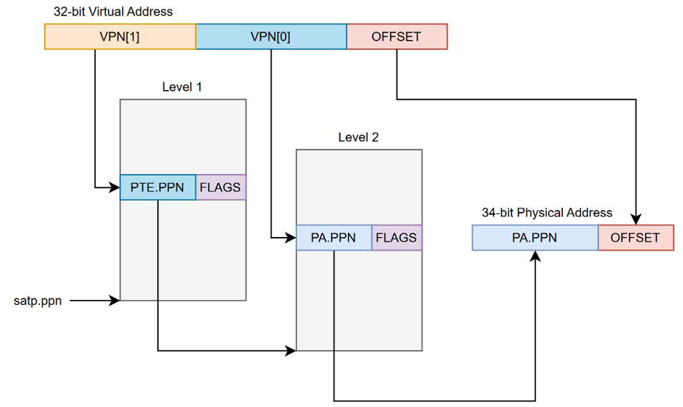
The L1 cache and TLB will be accessed in parallel. This means we opted for a virtually indexed, physically tagged (VIPT) cache design. The cache size must not be larger than it’s associativity multiplied by the page size (4KB) for a VIPT design to work without aliasing.

The TLB will be store the physical page number for a virtual page along with its permissions. TLB entries are matched against the stored address space identifier (ASID), a unique value for each program, along with the tag for the cache access.
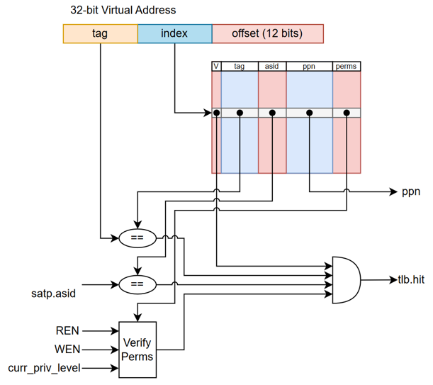
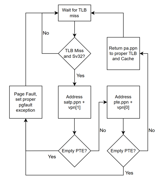
A hardware page walker is used to walk pages without the extra bits software page walks would add. Below is the general flow that our page walker uses to determine if two-level address translation is completed.
Status
As of December 2024, the TLB, PW, VIPT L1$, and CSRs + interrupt/exception handling have all been implemented into the processor. We feel the core at its current state needs to undergo extensive verification before we can consider proceeding with adding the hypervisor extension, which is why we are deciding not to move forward with implementing the hypervisor for Spring 2025.
Future Work
Instead, we will verify that the supervisor extension works in it entirety as a single-core using SystemVerilog test benches and S-Mode unit tests. Then, get it working as a multi-core. Once both single-core and multi-core function is perfected, we will get an operating system running on the processor and flash the design to an FPGA to have a “physical” deliverable. We also intend to perform a synthesis run of the design using the SkyWater 130nm PDK to determine the max operating frequency, power consumption, and area for the design. After this, the Spring semester will be completed, and we should have a solid supervisor implemented for this RISC-V core. The next steps would be implementing the Hypervisor extension for those brave enough.
Contibutors
- William Cunningham (wrcunnin@purdue.edu)
- William Milne (milnew@purdue.edu)
- Kathy Niu (niu59@purdue.edu)
RISC-V Supervisor Extension Hardware and Software Tests
Hardware Tests
1. TLB (Direct Mapped)
- Address translation off (M-mode and S-mode Bare Addressing)
- Compulsory TLB Miss
- TLB Hit
- TLB Eviction
- Mismatch ASID miss
- Invalidate TLB entries, by VA & ASID
- Invalidate TLB entries, by VA
- Invalidate TLB entries, by ASID
- Invalidate TLB entries, all entries
- Address translation off (again)
2. TLB (2-Way Set Associative, only used in this test)
- Address translation off (M-mode and S-mode Bare Addressing)
- Compulsory TLB Miss (empty set)
- Half-full set, TLB Hit
- Half-full set, TLB miss
- Full set, TLB hit
- Full set, TLB eviction (conflict miss)
- Mismatch ASID miss
- Invalidate TLB entries, by VA & ASID
- Invalidate TLB entries, by VA
- Invalidate TLB entries, by ASID
- Invalidate TLB entries, all entries
- Address translation off (again)
3. Page Permission Checking
All:
- Fault -> Invalid page
- Fault -> Not readable, but writeable
- Fault -> Reserved bits are set
- Fault -> Level == 0 and no RWX bits are set
- Fault -> U = 1, in S-Mode, and mstatus.sum = 0
- Fault -> U = 0, in U-Mode
- No Fault -> Level != 0, sv32 = 0, should NEVER EVER happen in RV32
- Fault -> Level != 0, sv32 = 1, pte_sv32.ppn[9:0] != 0
- No Fault -> U = 1, in S-Mode, and mstatus.sum = 1
- No Fault -> U = 1, in U-Mode
- No Fault -> Level != 0, sv32 = 1, pte_sv32.ppn[9:0] == 0 Loads:
- Fault -> R = 0, W = 0, X = 0, mstatus.mxr = 0
- Fault -> R = 0, W = 0, X = 0, mstatus.mxr = 1
- Fault -> R = 0, W = 0, X = 1, mstatus.mxr = 0
- No Fault -> R = 0, W = 0, X = 1, mstatus.mxr = 1
- Fault -> R = 0, W = 1, X = 0, mstatus.mxr = 0
- Fault -> R = 0, W = 1, X = 0, mstatus.mxr = 1
- Fault -> R = 0, W = 1, X = 1, mstatus.mxr = 0
- Fault -> R = 0, W = 1, X = 1, mstatus.mxr = 1
- No Fault -> R = 1, W = 0, X = 0
- No Fault -> R = 1, W = 0, X = 1
- No Fault -> R = 1, W = 1, X = 0
- No Fault -> R = 1, W = 1, X = 1 Stores:
- Fault -> R = 0, W = 0, X = 0
- Fault -> R = 0, W = 0, X = 1
- Fault -> R = 0, W = 1, X = 0
- Fault -> R = 0, W = 1, X = 1
- Fault -> R = 1, W = 0, X = 0
- Fault -> R = 1, W = 0, X = 1
- No Fault -> R = 1, W = 1, X = 0
- No Fault -> R = 1, W = 1, X = 1 Instructions:
- Fault -> R = 0, W = 0, X = 0
- No Fault -> R = 0, W = 0, X = 1
- Fault -> R = 0, W = 1, X = 0
- Fault -> R = 0, W = 1, X = 1
- Fault -> R = 1, W = 0, X = 0
- No Fault -> R = 1, W = 0, X = 1
- Fault -> R = 1, W = 1, X = 0
- No Fault -> R = 1, W = 1, X = 1
4. Page Walker
- Walk to get page
- Walk to get megapage
- Walk to get gigapage (RV64 only)
- Walk to get terapage (RV64 only)
- Walk to get petapage (RV64 only)
- Page walk fault, mid-level page not allocated
- Page walk fault, final-lebel page not allocated
- Page walk fault, improper read permissions
- Page walk fault, improper write permissions
- Page walk fault, improper execute permissions
- Page walk fault, improper dirty permissions
- Page walk fault, improper access permissions
- Page walk fault, improper valid permissions
5. TLB + Page Walker
- TLB miss, walk to get page
- TLB miss, walk to get megapage
- TLB miss, walk to get gigapage (RV64 only)
- TLB miss, walk to get terapage (RV64 only)
- TLB miss, walk to get petapage (RV64 only)
- TLB hit on all page types, no walk
- TLB miss, page walk fault (page not allocated)
- TLB miss, page walk fault (bad permissions)
6. TLB + VIPT L1$ + Page Walker
- Cache miss, TLB miss, walk to get page, handle cache miss
- Cache miss, TLB hit, handle cache miss
- Cache hit, TLB hit, no walk
- Invalidate TLB entry, Cache hit, TLB miss, walk to get page, cache hit
- Invalidate TLB entry, change page mapping, Cache hit, TLB miss, walk to get page, cache miss
7. I$/ITLB + D$/DTLB + Page Walker
- Compulsory misses, Data walk, instruction walk, data memory access, instruction memory access
- I/D $ misses, no page walk, data memory access, instruction memory access
- Full hits, no page walk, no memory access
Multicore
A multicore design is a type of multiprocessing in which multiple cores are used to run programs in parallel. This is sometimes referred to as chip multiprocessing (CMP). Multicore designs generally offer greater performance at the cost of power and area.
Heterogenous Multicore
A heterogenous multicore system uses disparate core designs and features to provide multiprocessing. This allows for greater task level parallelism without the power and area overhead that a homogenous design requires. Currently, a dual-core big/little design is planned.
Planned heterogenous core features
- 3 stage pipeline RV32IMACV big core
- 2 stage pipeline RV32EAC little core
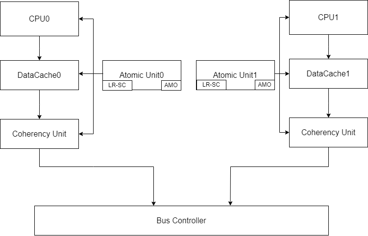
Current architecture plan for the Dual-core processor with MESI Coherence
Cache coherence
Incoherency can arise when programs acting on shared memory execute on a system
using private caches which do not synchronize with each other. An example of
this is shown below. Total program order in the example below is used to
sequentialize operations occuring in parallel. Both processors are running the
same program which loads a global variable, adds 100 to it, and then stores it
back to memory. Initially, processor 2 has the value at 0(sp) in its cache.
Processor 1 loads in 0(sp) into its cache and the a0 register. It then adds
100 to a0 which brings its value to 200. Finally, it stores the value back to
the same address of 0(sp). However, this causes an incoherence in the caches
of processors 1 and 2 because the value in processor 2’s cache is still 100.
Processor 2 then loads the value of 100 from its cache into its a0 register.
It then adds 100 to it, and again stores it back to memory.
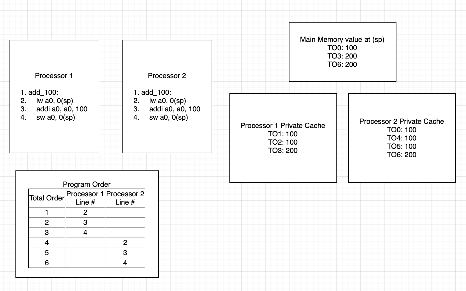
An example of coherent system running the same program is shown below. The
runtime state is mostly the same until total program order 3 in which processor
1 stores 200 to 0(sp). When this happens, this also updates the value in
processor 2’s cache to 200. Then, when it loads the value from memory in total
program order 4, it loads the updated value of 200 to its a0 register. Then,
when it adds 100 to it and stores it, it stores the correct value of 300.

Cache Modifications
To enable coherency and atomics, a reservation set register, a duplicate SRAM tag array, and a coherency interface were added to each L1 cache. Each cache is connected to an atomicity unit that handles bus transactions. This is intended to reduce the complexity of the cache and allows other cache designs to be used with few coherency-related modifications.
The coherency interface grants read-only access to the duplicate SRAM array to the bus. This allows the bus to compare tags when snooping without interrupting the cache. The bus only gains access to the cache’s SRAM data array if a snoop hit occurs, causing the cache FSM to enter a snooping state. The signals provided by the coherency interface, bus_ctrl_if, are available in the source_code/include/bus_ctrl_if.
Currently, the duplicate SRAM array contains both the data and the tags. This duplicate data is not used, so the extra SRAM cells used to store them will need to be removed. Additionally, the seperate_caches.sv file in the source_code/caches/ directory can be modified to use a cache without coherency for the Icache. At present, both the Dcache and Icache use the same L1 module.
Atomics
Atomic instructions can be used to provide memory ordering and ensure that a read-modify-write operation occurs as a single instruction. Memory ordering restrictions can be used to ensure whether or not certain instructions can be observed to have taken place by the time the atomic instruction executes. The table below briefly covers the semantics behind each ordering. Furthermore, a store-acquire or load-release operation would be semantically meaningless due to how data dependencies could be observed. It does not matter if a store is done with acquire semantics because stores in atomic contexts are used for ordering with respect to a previous load-acquire. Similarly, a load-release is nonsensical because it is not useful to have execution continue based off of future loads/stores.
A simple mental model which can be used to understand these orderings is how they would be used in a mutex. For example, when acquiring a mutex, we want all previous state to have completed so that the critical path relies on the most up to date information. When releasing the mutex, we want anyone who depends on the data behind the mutex to have the most up to date data from the execution of the critical path.
| Memory Ordering | Description |
|---|---|
| Relaxed | No ordering with respect to any other loads occurs. |
| Acquire (acq) | Ensures that no following memory operations can be observed to have happened before this operation. |
| Release (rel) | Ensures that all previous memory operations must be observed to have happened before this operation. |
| Acquire-Release (acqrel) | Ensures that all previous memory operations must be observed, and no following memory operations can be observed to have happened before this operation (sequentially consistent). |
It should be noted that these orderings are mostly relevant for out-of-order cores or for cores with out of order load-store queues. The current core is an in-order pipeline with no load-store queue therefore there is no support needed for these orderings.
Hardware atomics
Hardware atomics are planned to be implemented through a LRX, SC_AND_OP
microop execution sequence. The LRX microinstruction will be used to perform
a load-reserved with an exclusive bit set which would block any other
transactions on that cache line. The SC_AND_OP microinstruction would use the
results from the free ALU to be used as the store value the memory stage. As
with all SC’s, this clears the reservation set on that cache line.
Another interesting architecture is to attach an atomic unit to the bus, however, this would likely be unnecessary for our small scale dual core system. Information on this architecture can be found here.
Software emulated atomics
Because LR/SC are the basic building blocks of all atomic instructions,
a tight loop consisting of an LR, operation, and SC can be used to emulate
any AMO. An LR can be followed by a sequence of instructions to emulate the
effects of an AMO, which is then followed by an SC and a conditional jump
back to the LR can be used to retry the execution of an AMO until the SC
succeeds.
The core currently has support for the entire atomic instruction extension
through the use of the C routines in
verification/asm-env/selfasm/c/amo_emu.c. This file sets up an exception
handler for emulating atomic extension instructions in the case of illegal
instruction exceptions. The trap handler pushes all the registers to the stack,
decodes the instruction, executes it and updates the saved register on the
stack, then pops all the registers from the stack and returns. Support macros
for assembly usage are in verification/asm-env/selfasm/amo_emu.h. The
WANT_AMO_EMU_SUPPORT macro can be used to set up some support for the
C runtime including setting up the stack and exception handler. This allows for
trapping any encountered atomic instructions and emulating them using LR/SC
loops. This can be used as a stopgap until the hardware implementation of
atomics is completed.
Extensions
RISC-V defines many ISA extensions. Some add extra instructions, such as the “M” extension that adds multiply and divide instructions. Some add extra state, such as the “F” extension that adds a new floating point register file. Some assert properties about the microarchitecture, such as the “Ztso” extension that indicates the implementation follows the total store order memory consistency model.
To allow configurability, extensions must be implemented in a way that makes them easy to enable or disable as desired.
Most extensions implemented in RISCVBusiness will add an extra functional unit, and require decoding new instruction types. Extension implementation can be broken down into the following steps:
- Implement the new functional unit
- Implement a decoder that understands only the new instruction types.
- Create a wrapper file that conditionally either instantiates the new functional unit, or assign all outputs to ‘0’ (for disabled)
- Add your new decoder to
source_code/standard_core/control_unit.sv. Your new decoder must assert a ‘claim’ signal to indicate that an instruction belongs to that extension. Your decoder must generate all the needed control signals for your functional unit, and generate a ‘start’ signal to tell it to start working on the computation. - Instantiate your functional unit wrapper in the execute stage.
Walkthrough: Adding a Custom Extension
This walkthrough demonstrates how to add a custom extension by implementing a simple DELAY instruction that stalls the CPU for 100 cycles. This example uses the CUSTOM-0 opcode space (0x0B) reserved by RISC-V for custom extensions. (Note: This is a custom instruction for documentation purposes, and is not actually implemented.)
File Structure
For an extension named “delay”, you would create:
source_code/
├── packages/
│   └── rv32delay_pkg.sv       // Type definitions
└── rv32delay/
    ├── rv32delay_decode.sv    // Decoder
    ├── rv32delay_enabled.sv   // Functional unit
    ├── rv32delay_disabled.sv  // Disabled stub
    └── rv32delay_wrapper.sv   // Wrapper
Step 1: Create the Package
File: source_code/packages/rv32delay_pkg.sv
package rv32delay_pkg;

    // CUSTOM-0 opcode (0x0B)
    localparam logic [6:0] RV32DELAY_OPCODE = 7'b0001011;

    // R-type instruction format
    typedef struct packed {
        logic [6:0] funct7;
        logic [4:0] rs2;
        logic [4:0] rs1;
        logic [2:0] funct3;
        logic [4:0] rd;
        logic [6:0] opcode;
    } rv32delay_insn_t;

    // Operation type
    typedef enum logic [2:0] {
        DELAY = 3'b000
    } rv32delay_op_t;

    // Decoder output
    typedef struct packed {
        logic select;
        rv32delay_op_t op;
    } rv32delay_decode_t;

endpackage
Step 2: Implement the Decoder
File: source_code/rv32delay/rv32delay_decode.sv
module rv32delay_decode (
    input [31:0] insn,
    output logic claim,
    output rv32delay_pkg::rv32delay_decode_t rv32delay_control
);
    import rv32delay_pkg::*;

    rv32delay_insn_t insn_split;

    assign insn_split = rv32delay_insn_t'(insn);

    // Claim any instruction with CUSTOM-0 opcode and funct3=000
    assign claim = (insn_split.opcode == RV32DELAY_OPCODE)
                && (insn_split.funct3 == 3'b000);

    assign rv32delay_control.select = claim;
    assign rv32delay_control.op = DELAY;

endmodule
Key point: The decoder “claims” instructions to prevent them from being treated as illegal. This claim signal is ORed with other extension claim signals in the control unit (see control_unit.sv).
Step 3: Implement the Functional Unit
File: source_code/rv32delay/rv32delay_enabled.sv
module rv32delay_enabled (
    input CLK,
    input nRST,
    input rv32delay_start,
    input rv32delay_pkg::rv32delay_op_t operation,
    input [31:0] rv32delay_a,
    input [31:0] rv32delay_b,
    output logic rv32delay_done,
    output logic [31:0] rv32delay_out
);
    import rv32delay_pkg::*;

    localparam DELAY_CYCLES = 100;

    logic [7:0] counter;
    logic counting;

    // Start counting when start is pulsed
    always_ff @(posedge CLK, negedge nRST) begin
        if (!nRST) begin
            counter <= '0;
            counting <= 1'b0;
        end else begin
            if (rv32delay_start && !counting) begin
                // Start new delay
                counter <= DELAY_CYCLES;
                counting <= 1'b1;
            end else if (counting && counter > 0) begin
                // Count down
                counter <= counter - 1;
            end else if (counting && counter == 0) begin
                // Done counting
                counting <= 1'b0;
            end
        end
    end

    // Assert done when not counting (or on last cycle)
    assign rv32delay_done = !counting || (counter == 1);
    assign rv32delay_out = 32'b0;  // No result value

endmodule
Key points:
- Multi-cycle operations deassert
donewhile busy - The execute stage will stall until
doneis asserted (viahazard_if.ex_busyinstage3_execute_stage.sv) - Single-cycle operations can keep
donehigh always
Step 4: Create the Disabled Stub
File: source_code/rv32delay/rv32delay_disabled.sv
module rv32delay_disabled (
    input CLK,
    input nRST,
    input rv32delay_start,
    input rv32delay_pkg::rv32delay_op_t operation,
    input [31:0] rv32delay_a,
    input [31:0] rv32delay_b,
    output rv32delay_done,
    output logic [31:0] rv32delay_out
);
    // Always ready, return zero
    assign rv32delay_done = 1'b1;
    assign rv32delay_out = 32'b0;
endmodule
Key point: The disabled module must have identical ports but just tie outputs to safe values. This is never actually used because the decoder is also disabled, but prevents compilation errors.
Step 5: Create the Wrapper
File: source_code/rv32delay/rv32delay_wrapper.sv
`include "component_selection_defines.vh"

module rv32delay_wrapper (
    input CLK,
    input nRST,
    input rv32delay_start,
    input rv32delay_pkg::rv32delay_op_t operation,
    input [31:0] rv32delay_a,
    input [31:0] rv32delay_b,
    output rv32delay_done,
    output logic [31:0] rv32delay_out
);
    import rv32delay_pkg::*;

    `ifdef RV32DELAY_SUPPORTED
    rv32delay_enabled RV32DELAY(.*);
    `else
    rv32delay_disabled RV32DELAY(.*);
    `endif

endmodule
Key point: The wrapper uses preprocessor conditionals to select between enabled/disabled modules based on build configuration. These are found in component_selection_defines.vh, which is in turn generated by the configuration YAML file with the config_core.py script.
Step 6: Integrate into Control Unit
File: source_code/standard_core/control_unit.sv
Add these changes:
Import the package:
import rv32delay_pkg::*;
Declare claim signal:
logic rv32delay_claim;
Instantiate decoder:
`ifdef RV32DELAY_SUPPORTED
rv32delay_decode RV32DELAY_DECODE(
    .insn(cu_if.instr),
    .claim(rv32delay_claim),
    .rv32delay_control(cu_if.rv32delay_control)
);
`else
assign cu_if.rv32delay_control = {1'b0, rv32delay_op_t'(0)};
assign rv32delay_claim = 1'b0;
`endif // RV32DELAY_SUPPORTED
Update claimed signal:
assign claimed = rv32m_claim || rv32a_claim || rv32b_claim || rv32zc_claim || rv32delay_claim;
Key point: Adding your claim signal to the claimed logic prevents instructions from being marked as illegal when your extension is enabled. The main decoder generates a maybe_illegal signal that is surpressed by any claim being asserted; maybe_illegal && !claimed implies the insturction is illegal.
Step 7: Integrate into Execute Stage
File: source_code/pipelines/stage3/source/stage3_execute_stage.sv
Declare signals:
logic rv32delay_done;
word_t rv32delay_out;
Instantiate wrapper:
rv32delay_wrapper RV32DELAY_FU (
    .CLK(CLK),
    .nRST(nRST),
    .rv32delay_start(cu_if.rv32delay_control.select && !hazard_if.mem_use_stall),
    .operation(cu_if.rv32delay_control.op),
    .rv32delay_a(rs1_post_fwd),
    .rv32delay_b(rs2_post_fwd),
    .rv32delay_done(rv32delay_done),
    .rv32delay_out(rv32delay_out)
);
Add to output mux:
always_comb begin
    if(cu_if.rv32m_control.select) begin
        ex_out = rv32m_out;
    end else if(cu_if.rv32b_control.select) begin
        ex_out = rv32b_out;
    end else if(cu_if.rv32delay_control.select) begin
        ex_out = rv32delay_out;
    end else begin
        ex_out = alu_if.port_out;
    end
end
Add to hazard detection:
assign hazard_if.ex_busy = (!rv32m_done && cu_if.rv32m_control.select)
                        || (!rv32delay_done && cu_if.rv32delay_control.select);
Key points:
- The start signal is gated with
!hazard_if.mem_use_stallto prevent spurious starts during pipeline stalls - Use
rs1_post_fwd/rs2_post_fwdinstead of raw register file outputs to respect data forwarding (seestage3_execute_stage.sv) - Multi-cycle functional units must contribute to
ex_busyor the pipeline won’t stall
Step 8: Add Interface Signals
File: source_code/include/control_unit_if.vh
Add your control signal bundle:
rv32delay_pkg::rv32delay_decode_t rv32delay_control;
Step 9: Add a .core file
**File: source_code/rv32delay/rv32delay.core
CAPI=2:
name: socet:riscv:rv32m:0.1.0
description: RV32M Extension for RISCVBusiness

filesets:
    rtl:
        depend:
            - "socet:riscv:riscv_include"
            - "socet:riscv:packages"
        files:
            - rv32delay_decode.sv
            - rv32delay_enabled.sv
            - rv32delay_disabled.sv
            - rv32delay_wrapper.sv
        file_type: systemVerilogSource

targets:
    default: &default
        filesets:
            - rtl
        toplevel: rv32delay_wrapper
At a minimum, your core file needs to have a default target listing all the files needed. You may have additional filesets and simulation targets for individual testing as well.
Step 10: Update core configuration
File: scripts/config_core.py
Finally, you need to add your extension to config_core.py so that it can be parsed from the YAML file and generate the correct preprocessor definitions to include in component_selection_defines.vh. If you are using a standard extension, it should suffice to add your extension to the list in the RISCV_ISA variable. Custom extensions will need to add a new key to the YAML file, check for it in config_core.py, and generate the appropriate preprocessor defines.
Summary Checklist
- Create package with opcodes and type definitions
- Implement decoder that claims your instructions
- Implement enabled module with functional unit logic
- Create disabled stub with same interface
- Create wrapper with conditional instantiation
- Integrate decoder into control unit
- Add claim signal to
claimedlogic - Integrate functional unit into execute stage (signals, instantiation, output mux)
- Add busy signal to hazard detection for multi-cycle ops
- Add control signals to
control_unit_if.vh - Update
config_core.pyto generate theRV32X_SUPPORTEDdefine
Reference: Existing Extensions
The codebase includes several extension implementations you can reference:
- RV32M (Multiply/Divide):
source_code/rv32m/- Multi-cycle operations with variable latency - RV32B (Bit Manipulation):
source_code/rv32b/- Single-cycle combinational logic - RV32Zicond:
source_code/rv32zc/- Simple conditional operations
History
Earlier versions of RISCVBusiness (including the original fork) used a different system to manage extensions, RISC-MGMT. RISC-MGMT treated extensions as plugins that hooked into the pipeline in the decode, execute, and memory stages and could control some chosen signals. The philosophy for RISC-MGMT was that extensions acted as their own execution pipelines, and the main pipeline just passed a “token” to track where the instruction was (as the execution was still single-issue, in-order).
RISC-MGMT had some distinct advantages:
- Extensions all saw the same interface to the processor, and could be written in a standardized format
- Custom instructions were simple to implement, as they worked identically to the standard extensions
However, it also had the disadvantage of being inflexible. The model would have worked well for extensions like “M” or “B” where isolated functional units were added, but extensions like “F” that add new architectural state, “C” that changed the way instruction fetch worked and re-used “I” decoding, and “A” that is tightly coupled to the cache implementation require tighter integration with the rest of the core.
The current configuration implementation is essentially “inlining” the RISC-MGMT idea into the pipeline so that we can have more flexibility at the cost of more difficult integration.
RV32A
See Multicore for information on the RV32A implementation, as it is tightly coupled with the cache coherence implementation.
Currenly, we support only the ‘Zalrsc’ subset of the A extension.
RV32C
The RV32C extension allows some common instructions to be expressed as a 16b instruction. These 16b instructions may be freely mixed with 32b instructions.
Implementation Status
Currently, the implementation covers the “C” extension, including the “Zfa” and “Zfd” subsets (decode-only). “Zcb” will be implemented in the near future.
The implementation is split into 2 components: the fetch buffer and the decompressor.
Fetch Buffer
The fetch buffer sits in front of the I$. It has 2 functions:
- Determine the next fetch address. The I$ supports only aligned 32b accesses, so the fetch buffer translates misaligned PC to the aligned address of the relevant data.
- Buffer unused data. If an I$ fetch yields a compressed instruction, the remaining 16b are buffered as they belong to either another compressed instruction, or are part of a full-size instruction.
The fetch buffer forms an FSM (Mealy) from the PC alignment (pc[1]) and the fetch buffer valid bit (fb.valid). The state transition diagram is as follows:
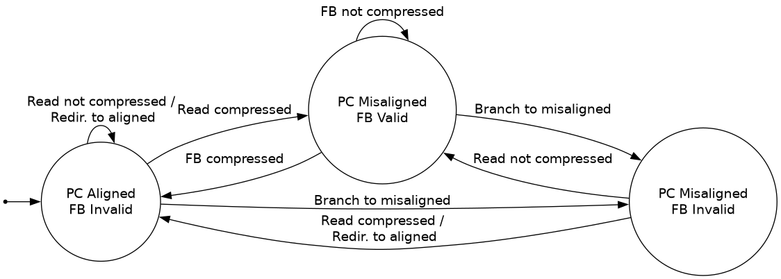
In this diagram, “read compressed” indicates the next instruction is a compressed instruction read from the I$. “FB compressed” means the next instruction is a compressed instruction that was held in the fetch buffer.
Note that the 4th combination, a valid fetch buffer and aligned PC, is not possible.
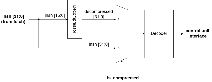
Decompressor
As all implemented instructions are 1:1 with full-sized instructions, the decompressor simply sits in front of the normal decoder. The decompressor takes in 16b of an instruction and outputs the corresponding 32b instruction.
